A button for smart lights
You can do two things when buying a knock-off product:
- Understand that you might be getting something inferior and accept it. You did willingly spend less money, after all. If you don’t want to do that though…
- You can turn it into a project — to create a (frankly overcomplicated) mess to cover up the inferiorities of the knock-off item you have purchased.
Will the second approach cost more money than the original project? Almost certainly. Will it be a fun teaching experience? It was in this case. So I can at least live with the illusion that I’ve made good decisions for one more day.
Smart lights - The Problem
The smart lights I currently own are not the Philips ones that are more commonly expected when one talks about smart lights. Now there are many off-brand smart lights, and I didn’t spend time comparing differences. I bought what was at a reasonable price at the time, especially with the chip shortage crisis that meant that Philips lights were 2-3x their usual price. I said to myself I’d upgrade once the ones I got burned out.
The problem was that these lights did not handle being disconnected from the network gracefully. If they couldn’t find a connection, they would go into their default reconnection mode. That would have been fine if that mode wasn’t to flash the brightest white light once a second.
The upshot of this was that the physical light switch became practically useless, and I would have to control my lights exclusively through my phone. This is because the physical light switch cuts the wifi connection from the bulbs and they go into reconnection mode immediately as they come back up instead of looking for the network first.
The Solution
The app to control the lights has a turn-off function. Invoking that would be good enough. I just had to figure out a way to translate the function call from the app, into a physical switch on my wall. It seemed simple enough at the time, and in retrospect it is, just the approach could be more elegant. But this was supposed to be a quick project, so the first (bodgy) solution is the final one, to match the quality of the original product.
The Parts
- IFTTT - Handles applet requests using WebHooks.
- SmartLife API - The app used by the lights manufacturer.
- ESP8266 NodeMCU - The (last) microcontroller used for the button control.
The Prototypes
Of all the items I needed, the only thing I didn’t have in hand was a Wi-Fi module. I already had an Arduino, so I thought I could get a standalone Wi-Fi module for the ESP8266, and that would have been enough to help me implement everything.
Having gotten the module, and wiring it up to the Arduino, I realised that I could not get it to make a POST request with an established library. There was an Arduino library that I used to control the Webhooks, but there was nothing that could send the request to the ESP82266 module. Instead, any commands to the module would have to be converted to AT commands. Another thing that came to light was that the combination of the Arduino and the breadboard with the module would make for a clunky and large button interface.
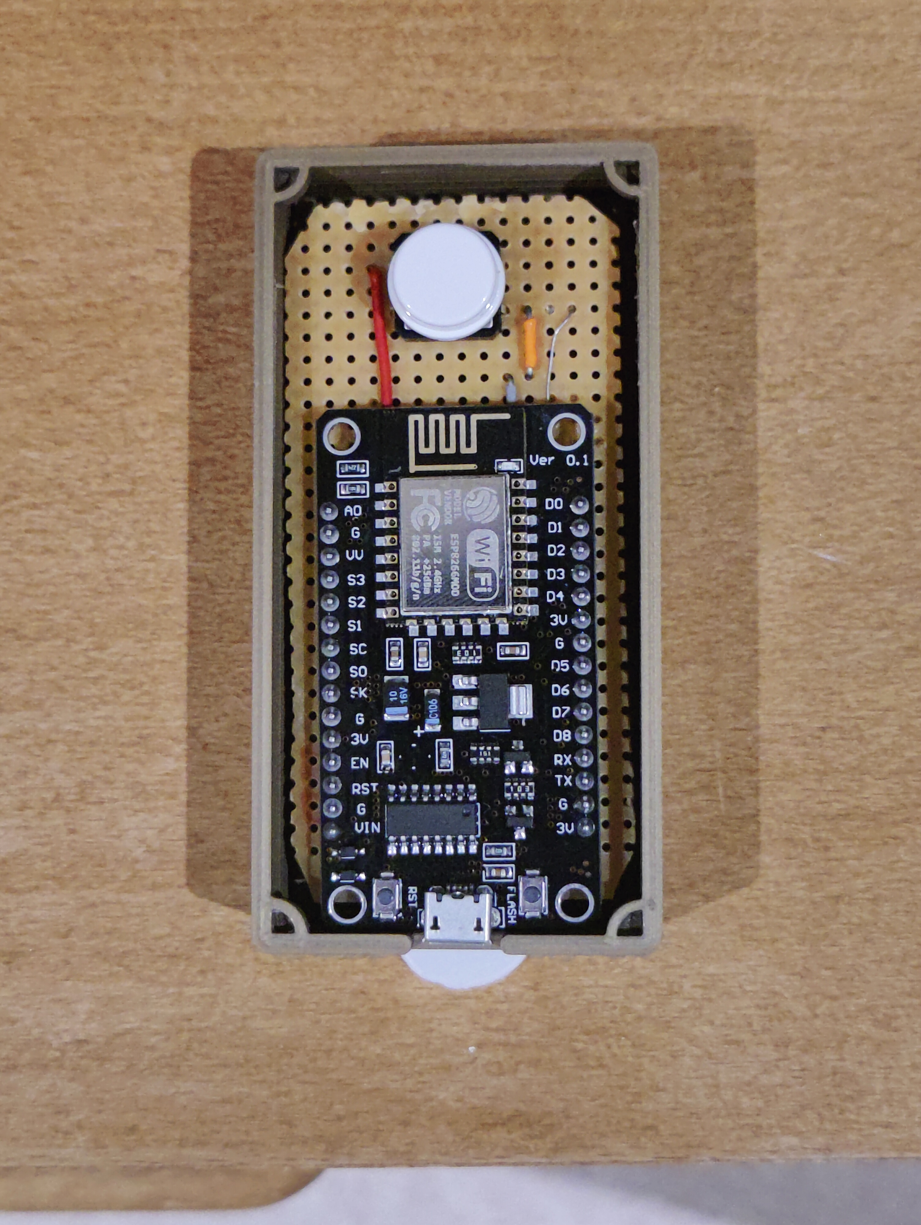
What could use my Webhooks code, however, was the ESP8366 NodeMCU which is an MCU with the module installed on it and in a much smaller package as well. The good news was that I could redevelop the code at this point in advance of the MCU appearing after I bought it.
Since all the prototyping was almost complete I moved on to veroboard, soldered everything in place to its small form factor and awaited for the NodeMCU to arrive. Version 2 of the system involved unpacking the MCU, plugging it in, and programming it with the code. A brief code snippet with the logic is summarised below, while the whole program can be found on Git Hub.
1
2
3
4
5
6
7
8
9
10
11
12
13
14
15
16
17
18
19
  //Initialise and connect to Wifi
  button.setDebounceTime(50);

  Serial.begin(115200);
  pinMode(LED_BUILTIN, OUTPUT);
  digitalWrite(LED_BUILTIN, LOW);
  WiFi.mode(WIFI_STA);
  WiFi.disconnect();
  delay(1000);
  ...

  void loop{

  button.loop();
  if(button.isPressed()){
    //Update the button state
    //Trigger off or on webhook based on the state
    }
  }
Product Management
The hackiest of equipment can look professional if the box is well-designed. I gather more evidence to confirm this claim, the more I investigate electronics by taking them apart. So naturally, to finalise this project I needed a nice box. This was a fun couple of hours in Solidworks, then exporting to STL files and 3D-printing using Ultimaker Cura.
First I made the bottom case with slots for the USB cable and holders for the header pins. I managed to make them tight enough that the Veroboard was essentially held in place by the groves and didn’t need any other fixtures. I didn’t quite get the four corners right where the bottom and top case parts would clip onto each other. I had to adjust and print a couple of versions until I was happy with it.
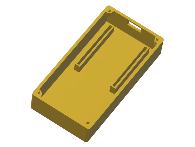 The bottom part of the case
The top part was fairly straightforward and only required two prints to get right. The hole for the button was just too tight by 1mm, so I had to increase the radius to make it less snug.
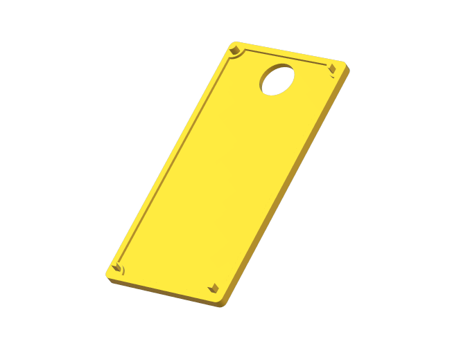 Top part of the case
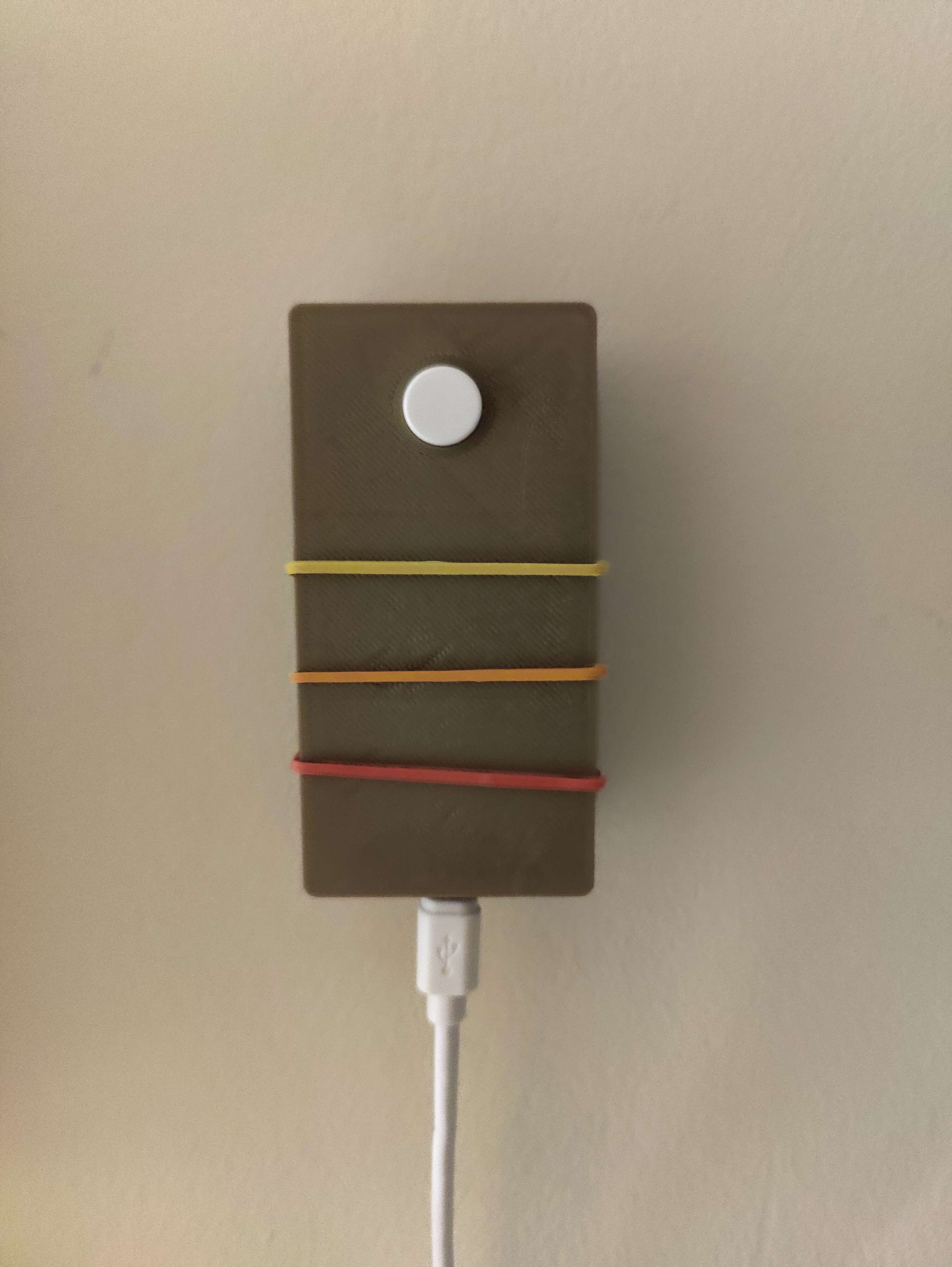
Outcome
Overall I’m happy with the final box after adding some extra decoration and a command strip to hold it in place. Now so long as the wall plug is on, I can physically press a button for my lights again. I still end up using the app more, but once in a while, it’s just much faster to hit a switch.